JBoss Tools 4.13.0 and Red Hat CodeReady Studio 12.13 for Eclipse 2019-09 are here and waiting for you. In this article, I’ll cover the highlights of the new releases and show how to get started.
Installation
Red Hat CodeReady Studio (previously known as Red Hat Developer Studio) comes with everything pre-bundled in its installer. Simply download it from our Red Hat CodeReady Studio product page and run it like this:
java -jar codereadystudio-<installername>.jar
JBoss Tools or Bring-Your-Own-Eclipse (BYOE) CodeReady Studio requires a bit more.
This release requires at least Eclipse 4.13 (2019-09), but we recommend using the latest Eclipse 4.13 2019-09 JEE Bundle because then you get most of the dependencies pre-installed.
Once you have installed Eclipse, you can either find us on the Eclipse Marketplace under “JBoss Tools” or “Red Hat CodeReady Studio.”
For JBoss Tools, you can also use our update site directly:
http://download.jboss.org/jbosstools/photon/stable/updates/
What’s new?
Our main focus for this release was improvements for container-based development and bug fixing. Eclipse 2019-06 itself has a lot of new cool stuff, but I’ll highlight just a few updates in both Eclipse 2019-06 and JBoss Tools plugins that I think are worth mentioning.
Red Hat OpenShift
OpenShift Container Platform 4.2 support
With the new OpenShift Container Platform (OCP) 4.2 now available (see the announcement), even if this is a major shift compared to OCP 3, Red Hat CodeReady Studio and JBoss Tools are compatible with this major release in a transparent way. Just define your connection to your OCP 4.2 based cluster as you did before for an OCP 3 cluster, and use the tooling!
CodeReady Containers 1.0 Server Adapter
A new server adapter has been added to support the next generation of CodeReady Containers 1.0. Although the server adapter itself has limited functionality, it is able to start and stop the CodeReady Containers virtual machine via its crc binary. Simply hit Ctrl+3 (Cmd+3 on OSX) and type new server, which will bring up a command to set up a new server.

Enter crc in the filter textbox.
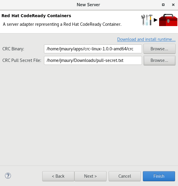
You should see the Red Hat CodeReady Containers 1.0 server adapter.
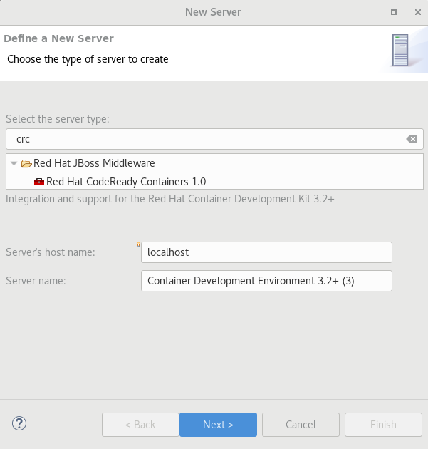
Select Red Hat CodeReady Containers 1.0 and click Next.
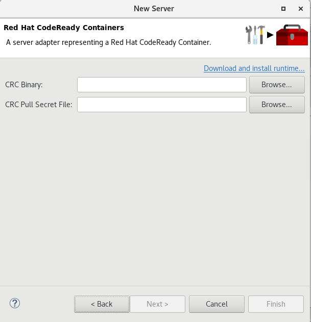
All you have to do is set the location of the CodeReady Containers crc binary file and the pull secret file location, which can be downloaded from https://cloud.redhat.com/openshift/install/crc/installer-provisioned.
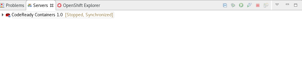
Once you’re finished, a new CodeReady Containers server adapter will then be created and visible in the Servers view.
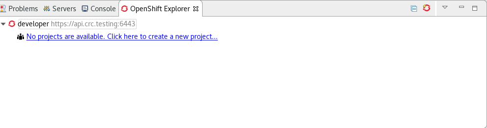
 Once the server is started, a new OpenShift connection should appear in the OpenShift Explorer view, allowing the user to quickly create a new Openshift application and begin developing their AwesomeApp in a highly replicatable environment.
 Server tools
Wildfly 18 Server Adapter
A server adapter has been added to work with Wildfly 18. It adds support for Java EE 8 and Jakarta EE 8.
EAP 7.3 Beta Server Adapter
A server adapter has been added to work with EAP 7.3 Beta.
Hibernate Tools
Hibernate Runtime Provider Updates
A number of additions and updates have been performed on the available Hibernate runtime providers.
The Hibernate 5.4 runtime provider now incorporates Hibernate Core version 5.4.7.Final and Hibernate Tools version 5.4.7.Final.
The Hibernate 5.3 runtime provider now incorporates Hibernate Core version 5.3.13.Final and Hibernate Tools version 5.3.13.Final.
Platform
Views, Dialogs and Toolbar
Quick Search
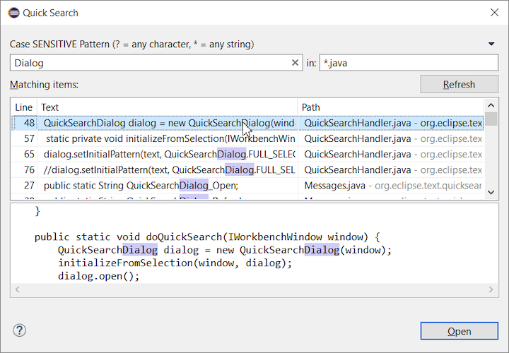
The new Quick Search dialog provides a convenient, simple and fast way to run a textual search across your workspace and jump to matches in your code. The dialog provides a quick overview showing matching lines of text at a glance. It updates as quickly as you can type and allows for quick navigation using only the keyboard. A typical workflow starts by pressing the keyboard shortcut Ctrl+Alt+Shift+L (or Cmd+Alt+Shift+L on Mac). Typing a few letters updates the search result as you type. Use Up-Down arrow keys to select a match, then hit Enter to open it in an editor.
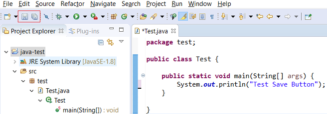
Save editor when Project Explorer has focus
You can now save the active editor even when the Project Explorer has focus. In cases where an extension contributes Saveables to the Project Explorer, the extension is honored and the save action on the Project Explorer will save the provided saveable item instead of the active editor.
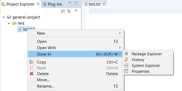
“Show In” context menu available for normal resources
The Show In context menu is now available for an element inside a resource project on the Project Explorer.
Show colors for additions and deletions in Compare viewer
In simple cases such as a two-way comparison or a three-way comparison with no merges and conflicts, the Compare viewer now shows different colors, depending on whether text has been added, removed, or modified. The default colors are green, red, and black, respectively.
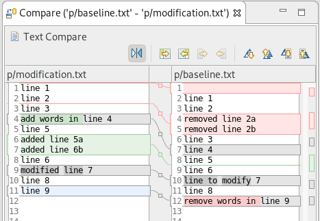
The colors can be customized through usual theme customization approaches, including using related entries in the Colors and Fonts preference page.
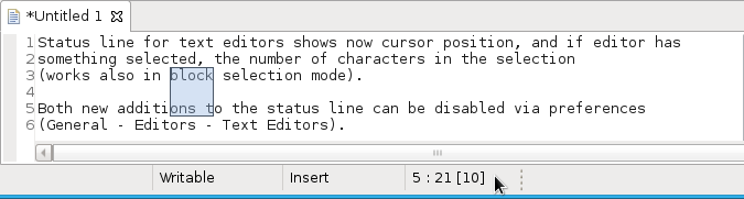
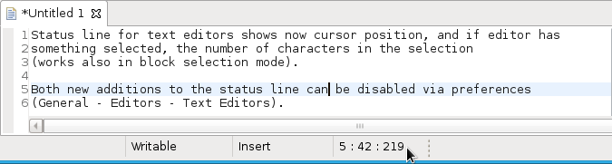
Editor status line shows more selection details
The status line for Text Editors now shows the cursor position, and when the editor has something selected, it shows the number of characters in the selection as well. This also works in the block selection mode.
These two new additions to the status line can be disabled via the General > Editors > Text Editors preference page.
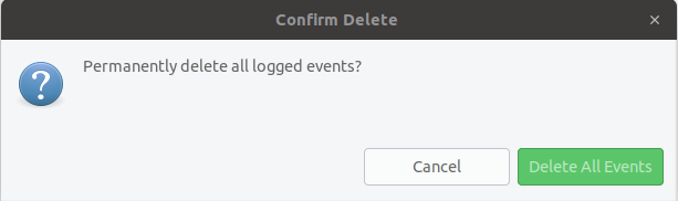
Shorter dialog text
Several dialog texts have been shortened. This allows you to capture important information faster.
Previously:
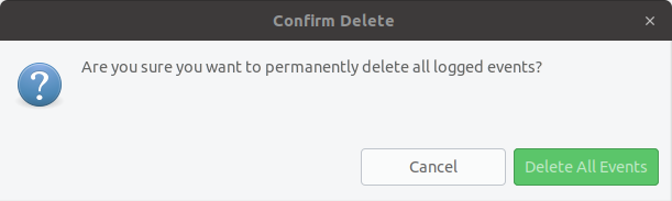
Now:
Close project via middle-click
In the Project Explorer, you can now close a project using middle-click.
Debug
Improved usability of Environment tab in Launch Configurations
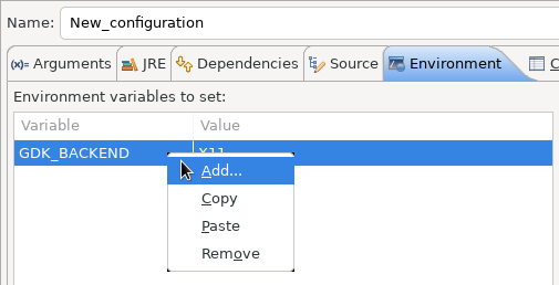
In the Environment tab of the Launch Configuration dialog, you can now double-click on an environment variable name or value and start editing it directly from the table.
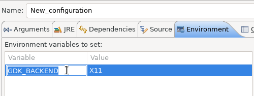
Right-clicking on the environment variable table now opens a context menu, allowing for quick addition, removal, copying, and pasting of environment variables.
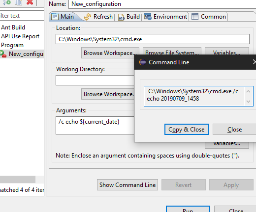
Show Command Line for external program launch
The External Tools Configuration dialog for launching an external program now supports the Show Command Line button.
Preferences
Close editors automatically when reaching 99 open editors
The preference to close editors automatically is now enabled by default. It will be triggered when you have opened 99 files. If you continue to open editors, old editors will be closed to protect you from performance problems. You can modify this setting in the Preferences dialog via the General > Editors > Close editors automatically preference.
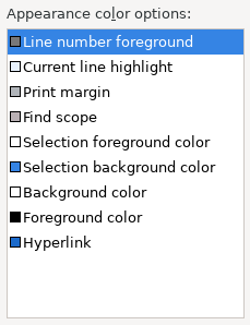
In-table color previews for Text Editor appearance color options
You can now see all the colors currently being used in Text Editors from the Appearance color options table, located in the Preferences > General > Editors > Text Editor page.
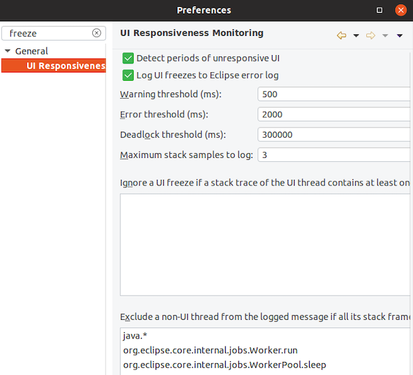
Automatic detection of UI freezes in the Eclipse SDK
The Eclipse SDK has been configured to show stack traces for UI freezes in the Error Log view by default for new workspaces. You can use this information to identify and report slow parts of the Eclipse IDE.
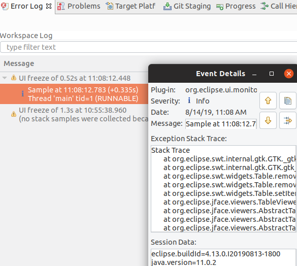
You can disable the monitoring or tweak its settings via the options in the General > UI Responsiveness Monitoring preference page as shown below.
Themes and Styling
Start automatically in dark theme based on OS theme
On Linux and Mac, Eclipse can now start automatically in dark theme when the OS theme is dark. This works by default, that is on a new workspace or when the user has not explicitly set or changed the theme in Eclipse.
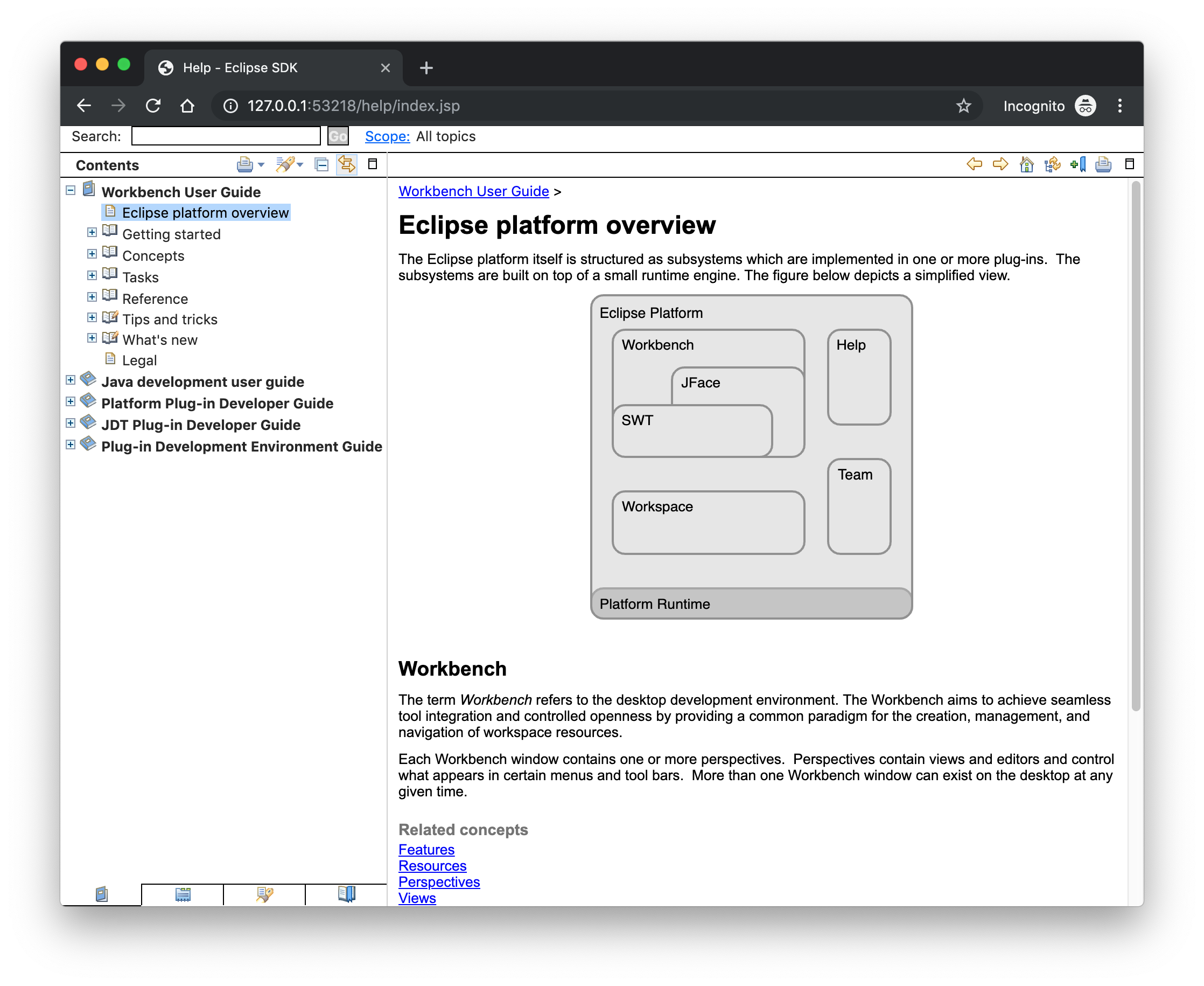
Display of Help content respects OS theme
More and more operating systems provide a system-wide dark theme. Eclipse now respects this system-wide theme setting when the Eclipse help content is displayed in an external browser. A prerequisite for this is a browser that supports the prefers-color-scheme CSS media query.
As of the time of writing, the following browser versions support it:
- Firefox version 67
- Chrome version 76
- Safari version 12.1
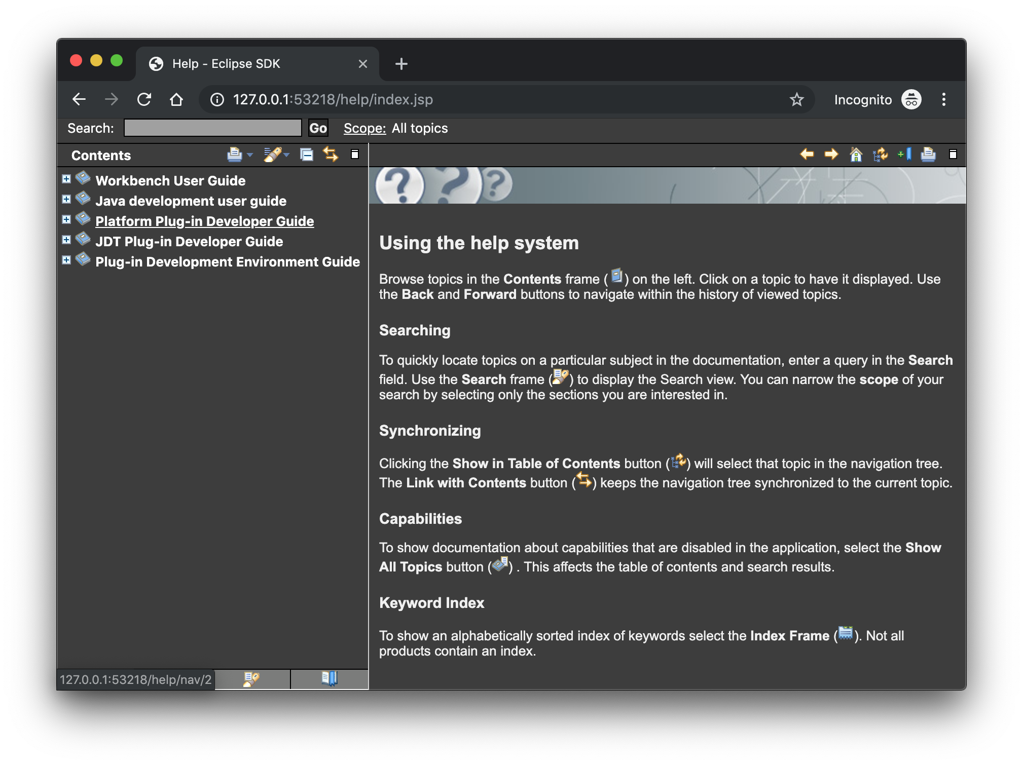 Help content uses high-resolution icons.
The Help System, as well as the help content of the Eclipse Platform, the Java Development Tooling, and the Plug-in Development Environment, now uses high-resolution icons. They are now crisp on high-resolution displays and also look much better in the dark theme.
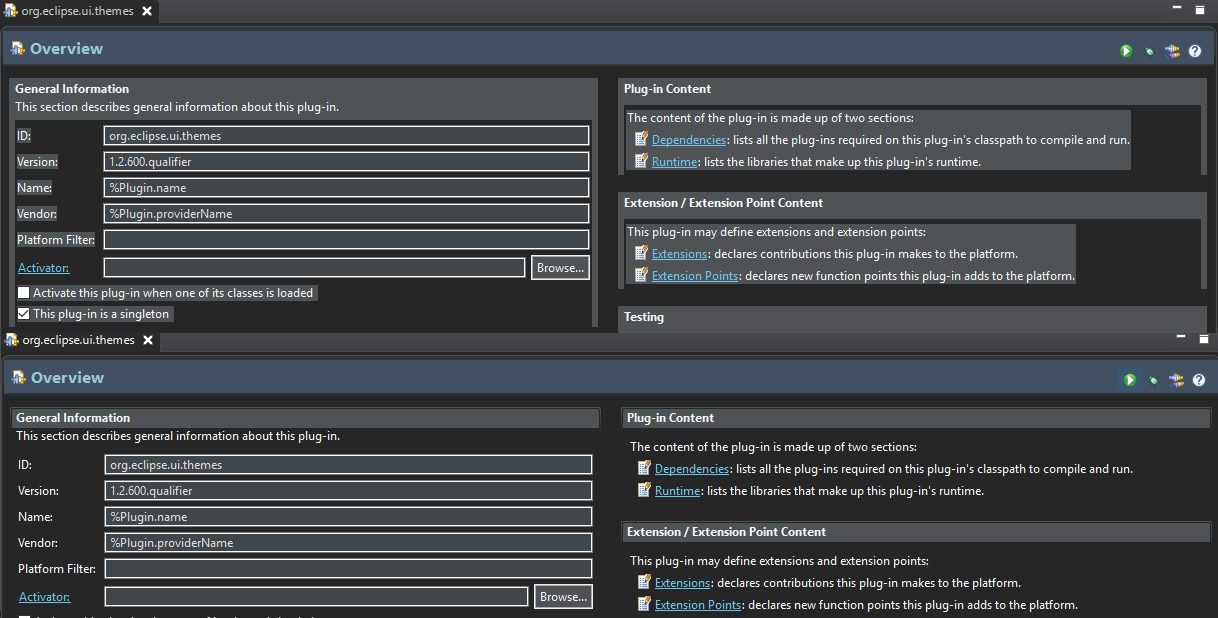
Improved dark theme on Windows
Labels, Sections, Checkboxes, Radio Buttons, FormTexts, and Sashes on forms now use the correct background color in the dark mode on windows.
General Updates
Interactive performance
Interactive performance has been further improved in this release and several UI freezes have been fixed.
Show key bindings when command is invoked
For presentations, screencasts, and learning purposes, it is very helpful to show the corresponding key binding when a command is invoked. When the command is invoked (via a key binding or menu interaction) the key binding, the command’s name and description are shown on the screen.
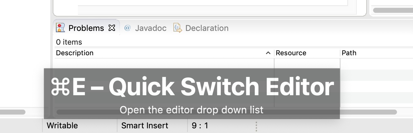
You can activate this in the Preferences dialog via the Show key binding when command is invoked checkbox on the General > Keys preference page. To toggle this setting quickly, you can use the Toggle Whether to Show Key Binding command (e.g., via the quick access).
Java Developement Tools (JDT)
Java 13 Support
Java 13 is out, and Eclipse JDT supports Java 13 for 4.13 via Marketplace.
The release notably includes the following Java 13 features:
- JEP 354: Switch Expressions (Preview).
- JEP 355: Text Blocks (Preview).
Please note that these are preview language features; hence, the enable preview option should be on. For an informal introduction of the support, please refer to Java 13 Examples wiki.
Java Views and Dialogs
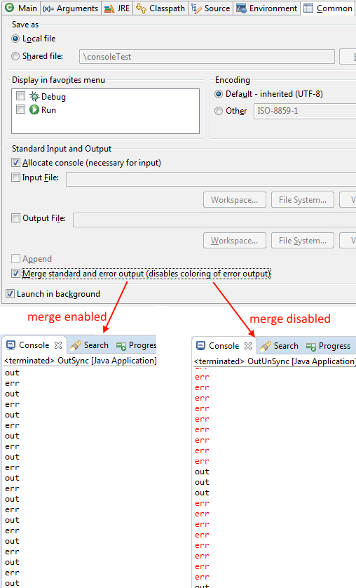
Synchronize standard and error output in console
The Eclipse Console view currently can not ensure that mixed standard and error output is shown in the same order as it is produced by the running process. For Java applications, the launch configuration Common tab now provides an option to merge standard and error output. This ensures that standard and error output is shown in the same order it was produced but also disables the individual coloring of error output.
Java Editor
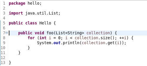
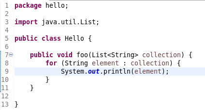
Convert to enhanced ‘for’ loop using Collections
The Java quickfix/cleanup Convert to enhanced ‘for’ loop is now offered on for loops that are iterating through Collections. The loop must reference the size method as part of the condition and if accessing elements in the body, must use the get method. All other Collection methods other than isEmpty invalidate the quickfix being offered.

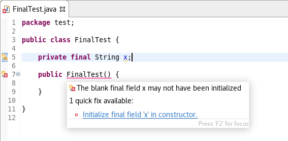
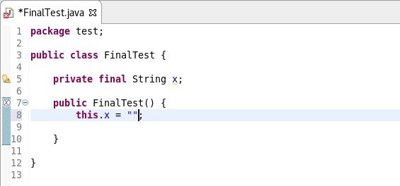
Initialize ‘final’ fields
A Java quickfix is now offered to initialize an uninitialized final field in the class constructor. The fix will initialize a String to the empty string, a numeric base type to 0, and, for class fields, it initializes them using their default constructor if available or null if no default constructor exists.
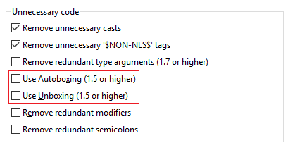
Autoboxing and Unboxing
Use Autoboxing and Unboxing when possible. These features are enabled only for Java 5 and higher.
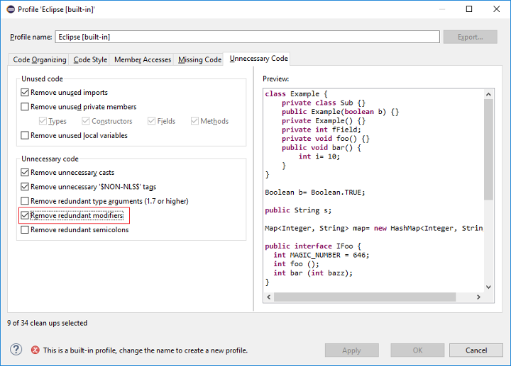
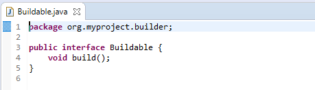
Improved redundant modifier removal
The Remove redundant modifier now also removes useless abstract modifier on the interfaces.
For the given code:
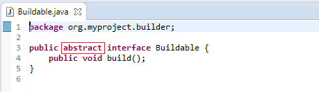
You get this:
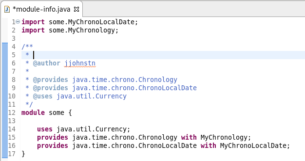
Javadoc comment generation for module
Adding a Javadoc comment to a Java module (module-info.java) will result in automatic annotations being added per the new module comment preferences.
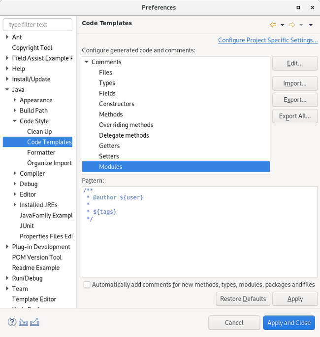
The $(tags) directive will add @uses and @provides tags for all uses and provides module statements.
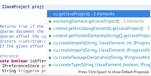
Chain Completion Code Assist
Code assist for “Chain Template Proposals” will be available. These will traverse reachable local variables, fields, and methods, to produce a chain whose return type is compatible with the expected type in a particular context.
The preference to enable the feature can be found in the Advanced sub-menu of the Content Assist menu group (Preferences > Java > Editor > Content Assist > Advanced).
Java Formatter
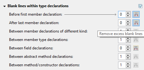
Remove excess blank lines
All the settings in the Blank lines section can now be configured to remove excess blank lines, effectively taking precedence over the Number of empty lines to preserve setting. Each setting has its own button to turn the feature on, right next to its number control. The button is enabled only if the selected number of lines is smaller than the Number of empty lines to preserve; otherwise, any excess lines are removed anyway.
Changes in blank lines settings
There’s quite a lot of changes in the Blank lines section of the formatter profile.
Some of the existing subsections and settings are now phrased differently to better express their function:
- The Blank lines within class declarations subsection is now Blank lines within type declaration.
- Before first declaration is now Before first member declaration.
- Before declarations of the same kind is now Between member declarations of different kind.
- Before member class declarations is now Between member type declarations.
- Before field declarations is now Between field declarations.
- Before method declarations is now Between method/constructor declarations.
More importantly, a few new settings have been added to support more places where the number of empty lines can be controlled:
- After last member declaration in a type (to complement previously existing Before first member declaration setting).
- Between abstract method declarations in a type (these cases were previously handled by Between method/constructor declarations).
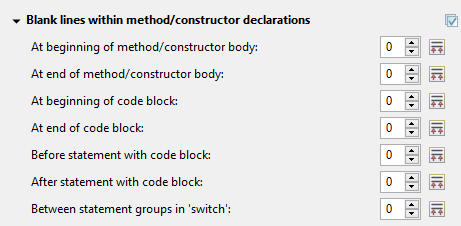
- At end of method/constructor body (to complement previously existing At beginning of method/constructor body setting).
- At beginning of code block and At end of code block.
- Before statement with code block and After statement with code block.
- Between statement groups in ‘switch.’
Most of the new settings have been put in a new subsection Blank lines within method/constructor declarations.
JUnit
JUnit 5.5.1
JUnit 5.5.1 is here and Eclipse JDT has been updated to use this version.
Debug
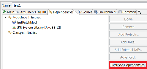
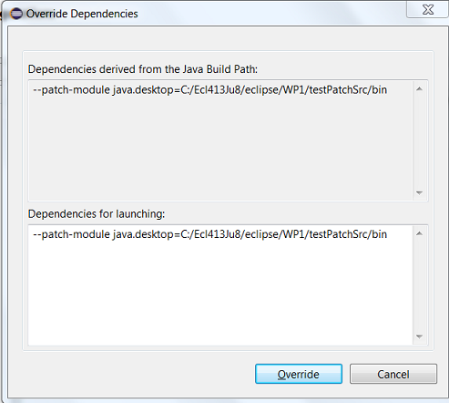
Enhanced support for –patch-module during launch
The Java Launch Configuration now supports patching of different modules by different sources during the launch. This can be verified in the Override Dependencies… dialog in the Dependencies tab in a Java Launch Configuration.
Java Build
Full build on JDT core preferences change
Manually changing the settings file .settings/org.eclipse.jdt.core.prefs of a project will result in a full project build, if the workspace auto-build is on. For example, pulling different settings from a git repository or generating the settings with a tool will now trigger a build. Note that this includes timestamp changes, even if actual settings file contents were not changed.
For the 4.13 release, it is possible to disable this new behavior with the VM property: -Dorg.eclipse.disableAutoBuildOnSettingsChange=true. It is planned to remove this VM property in a future release.
And more…
You can find more noteworthy updates in on this page.
What is next?
Having JBoss Tools 4.13.0 and Red Hat CodeReady Studio 12.13 out we are already working on the next release for Eclipse 2019-12.

The post New features in Red Hat CodeReady Studio 12.13.0.GA and JBoss Tools 4.13.0.Final for Eclipse 2019-09 appeared first on Red Hat Developer.