Fedora test days are events where anyone can help make certain that changes in Fedora work well in an upcoming release. Fedora community members often participate, and the public is welcome at these events. If you’ve never contributed to Fedora before, this is a perfect way to get started.
There are five upcoming test days in the next two weeks covering three topics:
Tues 28 March through Sunday 02 April, is to test the Fedora CoreOS.
Wed March 28th through March 31st , is to test the Upgrade
Monday April 03 through April 07 , is to test Fedora IoT .
Come and test with us to make Fedora 38 even better. Read more below on how to do it.
Fedora 38 CoreOS Test Week
The Fedora 38 CoreOS Test Week focuses on testing FCOS based on Fedora 38. The FCOS next stream is already rebased on Fedora 38 content, which will be coming soon to testing and stable. To prepare for the content being promoted to other streams the Fedora CoreOS and QA teams have organized test days on Tues, March 28, 2023 (results accepted through Sun , November 12). Refer to the wiki page for links to the test cases and materials you’ll need to participate. The FCOS and QA team will meet and communicate with the community sync on a Google Meet at the beginning of test week and async over multiple matrix/element channels. Read more about them in this announcement.
Upgrade test day
As we come closer to Fedora Linux 38 release dates, it’s time to test upgrades. This release has a lot of changes and it becomes essential that we test the graphical upgrade methods as well as the command line. As a part of these test days, we will test upgrading from a full updated, F36 and F37 to F38 for all architectures (x86_64, ARM, aarch64) and variants (WS, cloud, server, silverblue, IoT).
IoT test week
For this test week, the focus is all-around; test all the bits that come in a Fedora IoT release as well as validate different hardware. This includes:
Basic installation to different media
Installing in a VM
rpm-ostree upgrades, layering, rebasing
Basic container manipulation with Podman.
We welcome all different types of hardware, but have a specific list of target hardware for convenience.
How do test days work?
A test day is an event where anyone can help make certain that changes in Fedora work well in an upcoming release. Fedora community members often participate, and the public is welcome at these events. Test days are the perfect way to start contributing if you not in the past.
The only requirement to get started is the ability to download test materials (which include some large files) and then read and follow directions step by step.
Detailed information about all the test days are on the wiki page links provided above. If you are available on or around the days of the events, please do some testing and report your results.
Catching signals from others is how we have started communicating as human beings. It all started, of course, with our vocal cords. Then we moved to smoke signals for long-distance communication. At some point, we discovered radio waves and are still using them for contact. This article will describe how you can tune in using Fedora Linux and an SDR dongle.
My journey
I got interested in radio communication as a hobby when I was a kid, while my local club, LZ2KRS, was still a thing. I was so excited to be able to listen and communicate with people worldwide. It opened a whole new world for me. I was living in a communist country back then and this was a way to escape just for a bit. It also taught me about ethics and technology.
Year after year my hobby grew and now, in the Internet era with all the cool devices you can use, it’s getting even more exciting. So I want to show you how to do it with Fedora Linux and a hardware dongle.
What is Ham Radio
Amateur Radio (ham radio) is a popular hobby and service that brings people, electronics, and communication together. People use ham radio to talk across town, worldwide, or even into space, without the Internet or cell phones.
What’s SWLing?
To broadcast with your ham radio or SDR system, you need to obtain a license from a governmental body. But to intercept signals and listen to the open communication between two amateur radio stations, you don’t need one.
The term SWLing comes from the abbreviation of Short Wave Listener, where you listen to stations communicating in the shortwave bands between 3 and 30 MHz. This can be used for long-distance communication using the ionosphere, a layer of the Earth’s atmosphere.
To get started, you don’t need a license. Still, I recommend getting yourself an SWL sign to identify yourself in a listening contest. These are competitions for categories like who will discover the most connections in a month or who can listen to contacts from each country in the world.
How to get an SWL Sign?
There are two options:
Contact your national radio club and ask them to issue one for you. I got my Czech one, OK1-36568, after a few weeks.
You will get more information and help from either of these locations if you get stuck in some fashion!
QSL Cards
You can also use your sign to send QSL cards via post or electronically. This is a great way to communicate with people worldwide and make friends.
Per Wikipedia, A QSL card is a written confirmation of either a two-way radio communication between two amateur radio or citizens band stations; a one-way reception of a signal from an AM radio, FM radio, television, or shortwave broadcasting station; or the reception of a two-way radio communication by a third party listener (in our case).
A typical QSL card is the same size and made from the same material as a regular postcard; most are sent through snail mail.
Replace the radio receiver with your Fedora Linux.
The focal point of the ham radio hobby is the radio transmitter/receiver. Most of the time, enthusiasts build their radio from scratch, but this differs from what I will write about here.
SDR
A software-defined radio (SDR) system is a radio communication system that uses software for the modulation and demodulation of radio signals. In other words, a piece of hardware and software takes the place of a radio transmitter/receiver. This helps you discover more in a way that you are familiar with – a User Interface with built-in functions instead of the limited interface of a radio receiver.
My explanation oversimplifies things, so if you want to go deep and read more about SDR, here is an excellent start.
SDR Set Up under Fedora Linux
Choosing the proper hardware
If you search the Internet for an SDR dongle, you’ll find tons of ideas depending on your budget. In this tutorial, I’ll work with the one I have, which works well under Fedora 37 – it is available from Nooelec.
A note: The dongle covers frequencies from 25MHz to 1750MHz, which doesn’t cover the Short Wave bands. You would need an additional device to listen to them. This is included in the package I linked above. Some other hardware providers offer all-in-one products.
Check if the dongle is visible
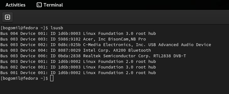
Before installing anything, detect whether Fedora Linux recognizes your USB dongle. I hope you didn’t buy a fake one :-). Use the following command to list the USB devices on your system.
lsusb
One of the output lines (in the case of Nooelec) should be
Realtek Semiconductor Corp. RTL2838 DVB-T
Now proceed by installing the software you need
Fedora offers a set of tools and drivers packaged as a group. Even though you would not use all the components in this package from the beginning, I recommend installing it. You’ll have more software to play with.
sudo dnf group install 'Electronic Lab'
I advise you to explore what’s in the group by running this command:
sudo dnf group info 'Electronic Lab'
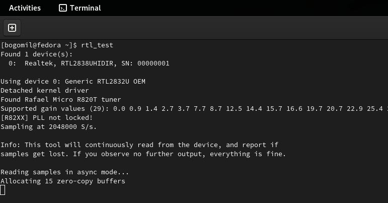
Now check if you have everything set up correctly by running:
rtl_test
You should see something like this:
Do not forget to kill this process because the device will be busy and cannot be used in the next step. A simple Ctrl + c works.
Gqrx
You have the dongle already in your device’s USB port and all the software you need to get started.
Now it’s time to intercept your first signal. Start the program called Gqrx. Don’t be alarmed by the strange interface. You’ll get used to it.
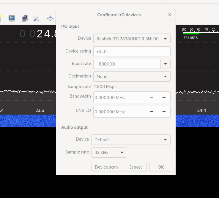
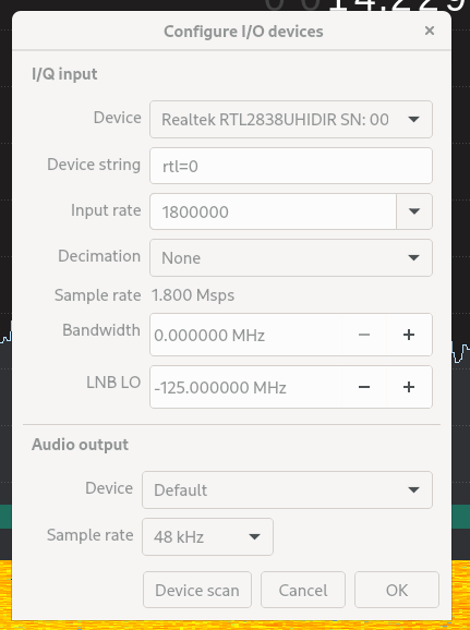
Configure the I/O Device Screen
From the “Device” Dropdown, select the ‘RealtekRTL2838...’
Leave the rest untouched for the moment.
If you don’t see your device there, click the “Device Scan” button at the bottom of the screen.
When your device is selected, click “OK” and the dialogue will close.
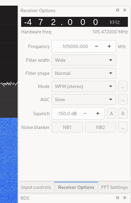
Configure the frequency screen
Before you start intercepting signals, ensure there is something out there that proves that everything works correctly. Since the dongle covers the FM radio band as well, do this:
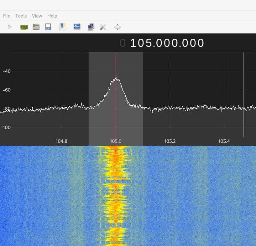
Locate your favorite radio station’s frequency. Mine is 105MHZ
Set it in the Frequency field
Select WFM (stereo) in the “Mode” dropdown. If you don’t do this, you will not hear a sound.
Play
And now, you need to start the reception by clicking the “play button” in your main menu. You will see the frequency visualized like this:
If you hear a sound, everything is ready to move to the next step.
If you don’t hear anything, check if everything is set up correctly. You may ask a questions in the comments for this article; I can direct you to the proper forum to solve this.
Feel free to play with some more FM broadcasts. You have the antenna for it in your pack.
Let’s go Short Wave
In the case of the Nooelec, you need to add one more device to the USB dongle and turn it on. Instructions on how to do that are included in the package you receive.
In short, you plug the “Up Converter” into your USB dongle and make sure the switch is in the “convert” position. Some videos are available on how to do it if you get stuck.
You will need an antenna and a good location
Now things get trickier. If you live in an area where you don’t see an open space out your window or other buildings surround your building, you might have trouble catching a Short Wave radio amateur signal.
Let’s try this to see if it works
Try to be in the open. I usually listen from my terrace, which could be better but works under particular conditions.
Apart from the hardware, you would need a long wire to act as your antenna. Try the antenna that comes with the hardware initially – the telescoping one from Nooelec, but it will catch only powerful signals.
Let’s go back to Gqrx
Now with the converter, you need to make some changes to your device screen:
Please note the –125Mhz for the LNB LO field. This is required for the Up Converter to work.
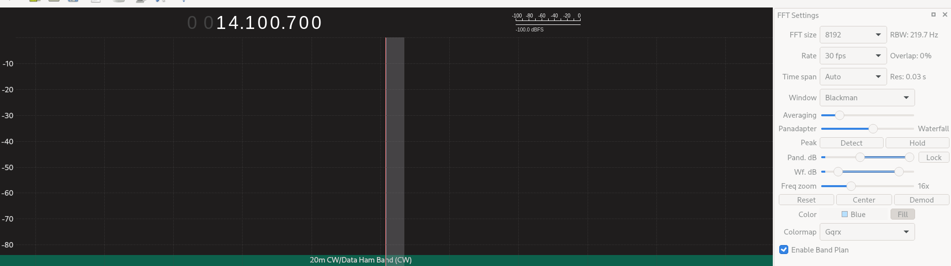
Tune your frequency to 14.100 Mhz and make sure your Mode is USB (standing for Upper sideband) because this is this band’s main demodulation option.
Then go to your FFT Settings screen, use the zoom slider, and set it to see about 100 kHz. In our case, you should have between 14.05 to 14.15 Mhz on your screen.
Also, click the “Enable Band Plan” to see the information about the SW bands you are exploring.
Then hit the play button and start exploring the space between 14.0 and 14.3 Mhz to get any amateur radio transmission.
When intercepting a transmission, adjust your settings to improve your listening experience. It’s a journey that you have already started.
Nowadays, the number of devices is getting bigger and bigger, and modern operating systems must try to support all types and several of them with every integration, with every release. Maintaining a large number of devices is difficult, expensive and also hard to test, specially for plug-and-play devices, like USB devices.
Therefore, it is necessary to create a mechanism to facilitate the maintenance and testing of old and new USB devices. And this is where USB device emulation comes in. In that way, a complete framework including a big bunch of emulated and validated USB devices will allow easier integration and release. The area of application would be very wide: earlier bug search/detection even during development, automatic tests, continuous integration, etc.
How to emulate USB devices
USB/IP project allows sharing the USB devices connected to a local machine so that they can be managed by another machine connected to the network by means of a TCP/IP connection.
Then USB/IP project consists of two parts:
local device support (host) to allow remote access to every necessary control events and data
remote control that catches every necessary control event and data to process like a normal driver
The procedure is valid for Linux and Windows, here I will focus only on Linux.
The idea behind emulation is to replace the remote device support with an application that behaves in the same way. In this way we can emulate devices with software applications that follow the commented USB/IP protocol specification.
In the following points I will describe how to configure and run the remote support and how to connect to our USB emulated device.
Remote support
Remote support is divided in two parts:
kernel space to control a remote device as it was local, that is, to be probed by the normal driver.
user space application to configure access to remote devices.
At this point, it is important to remark that the device emulators, after configuration by user space application, will communicate directly with the kernel space.
Local support has a very similar structure, but the focus of this article is device emulation.
Let’s analyze every part of remote support.
Kernel space
First of all, in order to get the functionality we need to compile the Linux Kernel with the following options:
CONFIG_USBIP_CORE=m
CONFIG_USBIP_VHCI_HCD=m
These options enable the USB/IP virtual host controller driver, which is run on the remote machine.
Normal USB drivers need to be also included because they will be probed and configured in the same way from virtual host controller drivers.
Besides there are other important configuration options:
These options define the number of ports per USB/IP virtual host controller and the number of USB/IP virtual host controllers as if adding physical host controllers. These are the default values if CONFIG_USBIP_VHCI_HCD is enabled, increase if necessary.
The commented options and kernel modules are already included in some Linux distributions like Fedora Linux.
Let’s see an example of available virtual USB buses and ports that we will use later.
Default and real resources in example equipment:
$ lsusb
Bus 002 Device 001: ID 1d6b:0003 Linux Foundation 3.0 root hub
Bus 001 Device 002: ID 0627:0001 Adomax Technology Co., Ltd
Bus 001 Device 001: ID 1d6b:0002 Linux Foundation 2.0 root hub
$ lsusb -t
/: Bus 02.Port 1: Dev 1, Class=root_hub, Driver=xhci_hcd/15p, 5000M
/: Bus 01.Port 1: Dev 1, Class=root_hub, Driver=xhci_hcd/15p, 480M
|__ Port 1: Dev 2, If 0, Class=Human Interface Device, Driver=usbhid, 480M
$
Now, we will load the module vhci-hcd into the system (default configuration for CONFIG_USBIP_VHCI_HC_PORTS and CONFIG_USBIP_VHCI_NR_HCS):
$ sudo modprobe vhci-hcd
$ lsusb
Bus 004 Device 001: ID 1d6b:0003 Linux Foundation 3.0 root hub
Bus 003 Device 001: ID 1d6b:0002 Linux Foundation 2.0 root hub
Bus 002 Device 001: ID 1d6b:0003 Linux Foundation 3.0 root hub
Bus 001 Device 002: ID 0627:0001 Adomax Technology Co., Ltd
Bus 001 Device 001: ID 1d6b:0002 Linux Foundation 2.0 root hub
$ lsusb -t
/: Bus 04.Port 1: Dev 1, Class=root_hub, Driver=vhci_hcd/8p, 5000M
/: Bus 03.Port 1: Dev 1, Class=root_hub, Driver=vhci_hcd/8p, 480M
/: Bus 02.Port 1: Dev 1, Class=root_hub, Driver=xhci_hcd/15p, 5000M
/: Bus 01.Port 1: Dev 1, Class=root_hub, Driver=xhci_hcd/15p, 480M
|__ Port 1: Dev 2, If 0, Class=Human Interface Device, Driver=usbhid, 480M
$
The remote USB/IP virtual host controller driver will only use the configured virtualized resources. Of course, emulated devices will work in the same way.
User space
The other necessary part in the USB/IP project is the user space tool usbip and needs to be used to configure the referred kernel space on both sides, although, in the same way, we only focus on the remote side, since the local side will be represented by the emulator.
That is, usbip tool will configure the USB/IP virtual controller (tcp client) in kernel space to connect to the device emulator (tcp server) in order to establish a direct connection between them for USB configuration, events, data, etc. exchange.
The tool is independent of the type of device and is able to provide information about available and reserved resources (see more information in the examples below).
The local USB/IP virtual host controller needs to specify the pair bus-port that will used for remote access, it will be the same for emulated devices, but in this case, this pair can be anything because there is no real device and resource reservation is not necessary.
This tool is found on the Linux Kernel repository in order to be totally synchronized with it.
Location of the tool on the Linux Kernel repository: ./tools/usb/usbip
In some distribution like Fedora Linux, the usbip utility can be installed by means of usbip package from repositories. If usbip utility or related package can not be found, follow the instruction in the available README file to compile and install. Suitable rpm package can also be generated from the usbip-emulatorrepository:
$ git clone https://github.com/jtornosm/USBIP-Virtual-USB-Device.git $ cd USBIP-Virtual-USB-Device/usbip $ make rpm ...
$
How to emulate USB devices
Emulators are generated in Python and C. I have started with C development (I will focus on this part), but the same could be done in Python.
For C development, compile emulation tools from the usbip-emulatorrepository:
$ git clone https://github.com/jtornosm/USBIP-Virtual-USB-Device.git $ cd USBIP-Virtual-USB-Device/c $ make ...
$
All the supported devices emulated at this moment will be generated:
hid-keyboard
hid-mouse
cdc-adm
hso
cdc-ether
bt
rpm package (usbip-emulator) can be also generated with:
$ make rpm ...
$
As examples, Vendor and Product IDs are hardcoded in the code.
Following three examples to show how emulation works. We are using the same equipment for the emulator and remote USB/IP but they could run in different equipment. Besides, we are reserving different resources so all the devices could be emulated at the same time.
Example 1: hso
From one terminal, let’s emulate the hso device:
(“1-1” is the pair bus-port for the USB device on the local machine, as we are emulating, it could be anything. It is only important because usbip tool will have to use the same name to request the emulated device)
(As we saw previously, for this example machine, bus 3 is virtualized)
$ ip addr show dev hso
0 3: hso0: <POINTOPOINT,MULTICAST,NOARP> mtu 1486 qdisc noop state DOWN group default qlen 10 link/none $ rfkill list 0: hso-0: Wireless WAN Soft blocked: no Hard blocked: no ...
$ lsusb ... Bus 003 Device 002: ID 0af0:6711 Option GlobeTrotter Express 7.2 v2 ... $ lsusb -t ...
/: Bus 03.Port 1: Dev 1, Class=root_hub, Driver=vhci_hcd/8p, 480M |__ Port 1: Dev 2, If 0, Class=Vendor Specific Class, Driver=hso, 12M ...
$
In order to release resources:
$ sudo usbip port
Imported USB devices
====================
Port 00: <Port in Use> at Full Speed(12Mbps)
Option : GlobeTrotter Express 7.2 v2 (0af0:6711)
3-1 -> usbip://127.0.0.1:3241/1-1
-> remote bus/dev 001/002
$ sudo usbip detach -p 00
usbip: info: Port 0 is now detached!
$
And we can check that the device is released:
$ ip addr show dev hso0 Device "hso0" does not exist. $ rfkill list ...
$ lsusb ... $
After this, we can emulate again or stop the emulated device from the first terminal (i.e. with Ctrl-C).
Example 2: cdc-ether
From one terminal, let’s emulate the cdc-ether device (root permission is required because raw socket needs to bind to specified interface for data plane):
(“1-1” is the pair bus-port for the USB device on the local machine, as we are emulating, it could be anything. It is only important because usbip tool will have to use the same name to request the emulated device)
(As we saw previously, for this example machine, bus 3 is virtualized)
$ ip addr show dev eth0 4: eth0: <BROADCAST,MULTICAST,UP,LOWER_UP> mtu 1500 qdisc fq_codel state UNKNOWN group default qlen 1000 link/ether 88:00:66:99:5b:aa brd ff:ff:ff:ff:ff:ff $ sudo ethtool eth0 ...
Link detected: yes $ lsusb ... Bus 003 Device 003: ID 0fe6:9900 ICS Advent ... $ lsusb -t ...
/: Bus 03.Port 1: Dev 1, Class=root_hub, Driver=vhci_hcd/8p, 480M |__ Port 2: Dev 3, If 0, Class=Communications, Driver=cdc_ether, 480M |__ Port 2: Dev 3, If 1, Class=CDC Data, Driver=cdc_ether, 480M ...
$
For this example, we can also test the data plane.
(IP forwarding is disabled in both sides)
First, we can configure the IP address in the emulated device:
$ sudo ip addr add 10.0.0.1/24 dev eth0
$ ip addr show dev eth0
4: eth0: <BROADCAST,MULTICAST,UP,LOWER_UP> mtu 1500 qdisc fq_codel state UNKNOWN group default qlen 1000
link/ether 88:00:66:99:5b:aa brd ff:ff:ff:ff:ff:ff
inet 10.0.0.1/24 scope global eth0
valid_lft forever preferred_lft forever
$
Second, for example, from other directly Ethernet connected machine (real or virtual) we can configure a macvlan interface in the same subnet to send/receive traffic (ping, iperf, etc.):
$ sudo ip link add macvlan0 link enp1s0 type macvlan mode bridge $ sudo ip addr add 10.0.0.2/24 dev macvlan0 $ sudo ip link set macvlan0 up $ ip addr show dev macvlan0 3: macvlan0@enp1s0: <BROADCAST,MULTICAST,UP,LOWER_UP> mtu 1500 qdisc noqueue state UP group default qlen 1000 link/ether d6:f1:cd:f1:cc:02 brd ff:ff:ff:ff:ff:ff inet 10.0.0.2/24 scope global macvlan0 valid_lft forever preferred_lft forever inet6 fe80::d4f1:cdff:fef1:cc02/64 scope link valid_lft forever preferred_lft forever $ ping 10.0.0.1 PING 10.0.0.1 (10.0.0.1) 56(84) bytes of data. 64 bytes from 10.0.0.1: icmp_seq=1 ttl=64 time=55.6 ms 64 bytes from 10.0.0.1: icmp_seq=2 ttl=64 time=2.19 ms 64 bytes from 10.0.0.1: icmp_seq=3 ttl=64 time=1.74 ms 64 bytes from 10.0.0.1: icmp_seq=4 ttl=64 time=1.76 ms 64 bytes from 10.0.0.1: icmp_seq=5 ttl=64 time=1.93 ms 64 bytes from 10.0.0.1: icmp_seq=6 ttl=64 time=1.65 ms ...
In order to release resources:
$ sudo usbip port Imported USB devices ==================== ...
Port 01: <Port in Use> at High Speed(480Mbps) ICS Advent : unknown product (0fe6:9900) 3-2 -> usbip://127.0.0.1:3245/1-1 -> remote bus/dev 001/003 $ sudo usbip detach -p 01 usbip: info: Port 1 is now detached! $
And we can check that the device is released:
$ ip addr show dev eth0
Device "eth0" does not exist.
$ lsusb
...
$
And of course, traffic from the other machine is not working:
From 10.0.0.2 icmp_seq=167 Destination Host Unreachable From 10.0.0.2 icmp_seq=168 Destination Host Unreachable From 10.0.0.2 icmp_seq=169 Destination Host Unreachable From 10.0.0.2 icmp_seq=170 Destination Host Unreachable ...
After this, we can emulate again or stop the emulated device from the first terminal (i.e. with Ctrl-C).
Example 3: bt
From one terminal, let’s emulate the Bluetooth device:
(“1-1” is the pair bus-port for the USB device on the local machine, as we are emulating, it could be anything. It is only important because usbip tool will have to use the same name to request the emulated device)
(As we saw previously, for this example machine, bus 3 is virtualized)
$ hciconfig -a hci0: Type: Primary Bus: USB BD Address: AA:BB:CC:DD:EE:11 ACL MTU: 310:10 SCO MTU: 64:8 UP RUNNING PSCAN ISCAN INQUIRY RX bytes:1451 acl:0 sco:0 events:80 errors:0 TX bytes:1115 acl:0 sco:0 commands:73 errors:0 Features: 0xff 0xff 0x8f 0xfe 0xdb 0xff 0x5b 0x87 Packet type: DM1 DM3 DM5 DH1 DH3 DH5 HV1 HV2 HV3 Link policy: RSWITCH HOLD SNIFF PARK Link mode: SLAVE ACCEPT Name: 'BT USB TEST - CSR8510 A10' Class: 0x000000 Service Classes: Unspecified Device Class: Miscellaneous, HCI Version: 4.0 (0x6) Revision: 0x22bb LMP Version: 3.0 (0x5) Subversion: 0x22bb Manufacturer: Cambridge Silicon Radio (10) $ rfkill list ...
1: hci0: Bluetooth Soft blocked: no Hard blocked: no $ lsusb ...
Bus 003 Device 004: ID 0a12:0001 Cambridge Silicon Radio, Ltd Bluetooth Dongle (HCI mode) ...
$ lsusb -t ...
/: Bus 03.Port 1: Dev 1, Class=root_hub, Driver=vhci_hcd/8p, 480M |__ Port 3: Dev 4, If 0, Class=Wireless, Driver=btusb, 12M |__ Port 3: Dev 4, If 1, Class=Wireless, Driver=btusb, 12M ...
$
And we can turn off and turn on the emulated Bluetooth device, detecting several fake Bluetooth devices:
(At this moment, fake Bluetooth devices are not emulated/simulated so we can not set up)
Turn Bluetooth offTurn Bluetooth on
In order to release resources:
$ sudo usbip port Imported USB devices ==================== ...
Port 02: <Port in Use> at Full Speed(12Mbps) Cambridge Silicon Radio, Ltd : Bluetooth Dongle (HCI mode) (0a12:0001) 3-3 -> usbip://127.0.0.1:3243/1-1 -> remote bus/dev 001/002 $ sudo usbip detach -p 02 usbip: info: Port 2 is now detached! $
And we can check that the device is released:
$ hciconfig $ rfkill list ...
$ lsusb ... $
And of course, device is not detected (as before emulation):
Bluetooth is not found
After this, we can emulate again or stop the emulated device from the first terminal (i.e. with Ctrl-C).
Emulated vs real USB devices
When the real hardware and/or final device is not used to test, we can always feel insecure about the results, and this is the biggest hurdle that we will have to overcome to check the correct operation of the devices by means of emulation.
So, in order to be confident, emulation must be as close as possible to the real hardware and in order to get the most real emulation every aspect of the device must be covered (or at least the necessary ones if they are not related with other aspects). In fact, for a correct test, we must not modify the driver, that is, we must only emulate the physical layer, so that the driver is not able to know if the device is real or emulated.
Starting to test with the real hardware device is a very good idea to get a reference to build the emulator with the same features. For the case of USB devices, the device emulator building is easier because of the existing procedure to get remote control that complies with all the characteristics mentioned above.
Conclusion
USB device emulation is the best way to integrate and test the related features in an efficient, automatic and easy way. But, in order to be confident about the emulation procedure, device emulators need to be previously validated to confirm that they work in the same way as real hardware.
Of course, the USB device emulator is not the same as the real hardware device, but the commented method, thanks to the tested procedure to get remote control of the device, it’s very close to the real scenario and can help a lot to improve our release and testing processes.
Finally, I would like to comment that one of the best advantages of using software emulators is that we will be able to cause specific behaviors, in a simple way, that would be very difficult to reproduce with real hardware, and this could help to find issues and be more robust.
Sometimes there is a need to add another disk to your system. This is where Logical Volume Management (LVM) comes in handy. The cool thing about LVM is that it’s fairly flexible. There are several ways to add a disk. This article describes one way to do it.
Heads up!
This article does not cover the process of physically installing a new disk drive into your system. Consult your system and disk documentation on how to do that properly.
Important: Always make sure you have backups of important data. The steps described in this article will destroy data if it already exists on the new disk.
Good to know
This article doesn’t cover every LVM feature deeply; the focus is on adding a disk. But basically, LVM has volume groups, made up of one or more partitions and/or disks. You add the partitions or disks as physical volumes. A volume group can be broken down into many logical volumes. Logical volumes can be used as any other storage for filesystems, ramdisks, etc. More information can be found here.
Think of the physical volumes as forming a pool of storage (a volume group) from which you then carve out logical volumes for your system to use directly.
Preparation
Make sure you can see the disk you want to add. Use lsblk prior to adding the disk to see what storage is already available or in use.
$ lsblk
NAME MAJ:MIN RM SIZE RO TYPE MOUNTPOINT
zram0 251:0 0 989M 0 disk [SWAP]
vda 252:0 0 20G 0 disk
├─vda1 252:1 0 1G 0 part /boot
└─vda2 252:2 0 19G 0 part
└─fedora_fedora-root 253:0 0 19G 0 lvm /
This article uses a virtual machine with virtual storage. Therefore the device names start with vda for the first disk, vdb for the second, and so on. The name of your device may be different. Many systems will see physical disks as sda for the first disk, sdb for the second, and so on.
Once the new disk has been connected and your system is back up and running, use lsblk again to see the new block device.
$ lsblk
NAME MAJ:MIN RM SIZE RO TYPE MOUNTPOINT
zram0 251:0 0 989M 0 disk [SWAP]
vda 252:0 0 20G 0 disk
├─vda1 252:1 0 1G 0 part /boot
└─vda2 252:2 0 19G 0 part
└─fedora_fedora-root 253:0 0 19G 0 lvm /
vdb 252:16 0 10G 0 disk
There is now a new device named vdb. The location for the device is /dev/vdb.
$ ls -l /dev/vdb
brw-rw----. 1 root disk 252, 16 Nov 24 12:56 /dev/vdb
We can see the disk, but we cannot use it with LVM yet. If you run blkid you should not see it listed. For this and following commands, you’ll need to ensure your system is configured so you can use sudo:
Initialize the disk using pvcreate. You need to pass the full path to the device. In this example it is /dev/vdb; on your system it may be /dev/sdb or another device name.
You can get a detailed list of the specific volume group and physical volumes as well:
$ sudo vgdisplay fedora_fedora
--- Volume group ---
VG Name fedora_fedora
System ID
Format lvm2
Metadata Areas 2
Metadata Sequence No 3
VG Access read/write
VG Status resizable
MAX LV 0
Cur LV 1
Open LV 1
Max PV 0
Cur PV 2
Act PV 2
VG Size 28.99 GiB
PE Size 4.00 MiB
Total PE 7422
Alloc PE / Size 4863 / 19.00 GiB
Free PE / Size 2559 / 10.00 GiB
VG UUID C5dL2s-dirA-SQ15-TfQU-T3yt-l83E-oI6pkp
Look at the PV:
$ sudo pvdisplay /dev/vdb --- Physical volume --- PV Name /dev/vdb VG Name fedora_fedora PV Size 10.00 GiB / not usable 4.00 MiB Allocatable yes PE Size 4.00 MiB Total PE 2559 Free PE 2559 Allocated PE 0 PV UUID 4uUUuI-lMQY-WyS5-lo0W-lqjW-Qvqw-RqeroE
Now that we have added the disk, we can allocate space to logical volumes (LVs):
Look at the logical volumes. Here’s a detailed look at the root LV:
$ sudo lvdisplay fedora_fedora/root
--- Logical volume ---
LV Path /dev/fedora_fedora/root
LV Name root
VG Name fedora_fedora
LV UUID yqc9cw-AvOw-G1Ni-bCT3-3HAa-qnw3-qUSHGM
LV Write Access read/write
LV Creation host, time fedora, 2020-11-24 11:44:36 -0500
LV Status available
LV Size 19.00 GiB
Current LE 4863
Segments 1
Allocation inherit
Read ahead sectors auto
- currently set to 256
Block device 253:0
Look at the size of the root filesystem and compare it to the logical volume size.
$ df -h /
Filesystem Size Used Avail Use% Mounted on
/dev/mapper/fedora_fedora-root 19G 1.4G 17G 8% /
The logical volume and the filesystem both agree the size is 19G. Let’s add 5G to the root logical volume:
$ sudo lvresize -L +5G fedora_fedora/root
Size of logical volume fedora_fedora/root changed from 19.00 GiB (4863 extents) to 24.00 GiB (6143 extents).
Logical volume fedora_fedora/root successfully resized.
We now have 24G available to the logical volume. Look at the / filesystem.
$ df -h /
Filesystem Size Used Avail Use% Mounted on
/dev/mapper/fedora_fedora-root 19G 1.4G 17G 8% /
We are still showing only 19G free. This is because the logical volume is not the same as the filesytem. To use the new space added to the logical volume, resize the filesystem.
$ sudo resize2fs /dev/fedora_fedora/root
resize2fs 1.45.6 (20-Mar-2020)
Filesystem at /dev/fedora_fedora/root is mounted on /; on-line resizing required
old_desc_blocks = 3, new_desc_blocks = 3
The filesystem on /dev/fedora_fedora/root is now 6290432 (4k) blocks long.
Look at the size of the filesystem.
$ df -h /
Filesystem Size Used Avail Use% Mounted on
/dev/mapper/fedora_fedora-root 24G 1.4G 21G 7% /
As you can see, the root file system (/) has taken all of the space available on the logical volume and no reboot was needed.
You have now initialized a disk as a physical volume, and extended the volume group with the new physical volume. After that you increased the size of the logical volume, and resized the filesystem to use the new space from the logical volume.
The kernel team is working on final integration for kernel 5.9. This version was just recently released, and will arrive soon in Fedora. As a result, the Fedora kernel and QA teams have organized a test week from Monday, October 26, 2020 through Monday, November 02, 2020. Refer to the wiki page for links to the test images you’ll need to participate. Read below for details.
How does a test week work?
A test week is an event where anyone can help make sure changes in Fedora work well in an upcoming release. Fedora community members often participate, and the public is welcome at these events. If you’ve never contributed before, this is a perfect way to get started.
To contribute, you only need to be able to do the following things:
Download test materials, which include some large files
Read and follow directions step by step
The wiki page for the kernel test day has a lot of good information on what and how to test. After you’ve done some testing, you can log your results in the test day web application. If you’re available on or around the day of the event, please do some testing and report your results. We have a document which provides all the steps written.
Happy testing, and we hope to see you on test day.
We’ve been teasing this for a while, but today it’s finally true—Fedora Workstation is now available preinstalled on the Lenovo ThinkPad X1 Carbon Gen 8, ThinkPad P53, and ThinkPad P1 Gen 2 laptops. The ThinkPad X1 Carbon is available today for direct consumer purchase from Lenovo’s online store. The Lenovo ThinkPad P1 Gen 2 and ThinkPad P53 will be available next week via the “Contact Us” icon on Lenovo.com. What’s more, the successor models are in the works for pre-load and online ordering as well!
Lenovo has been a great partner in bringing this to market. Like the Fedora community, they are operating on an “upstream first” model. That’s part of why the only thing you’ll see on the laptop that doesn’t come from an official Fedora repository is a set of PDFs providing documentation and legal notices. Lenovo engineers have been contributing to the Linux kernel, including a patch to enable the “lap mode” sensor, which is already accepted. They have also worked with their vendors to improve Linux support in devices like the fingerprint scanner.
Of course, you already know that open source is about more than just the technology; the community is what makes it great. Lenovo is a member of Fedora and other communities. In addition to participating in the usual Fedora places (like the devel mailing list), they also were a gold-level sponsor of our Nest With Fedora conference. And they have a dedicated Fedora section on their community forum. Mark Pearson, Senior Linux Developer said “doing open source the right way is important to us” at his Nest With Fedora Q&A session.
This will be a global program, but it will take some time to roll out country-by-country. If it doesn’t appear on the website in your country, call the local sales number for your country to place a phone order. I’m excited to have Lenovo offer Fedora Workstation as a supported choice on their laptops. This is a great opportunity to grow our community.
User data is the most important thing on a computer. Whether it’s source code for the next big release, family pictures, a music library, or anything else, you want it to be safe. Changing the default file system is not a change to make casually. The Fedora Project is changing the default file system for desktop variants (Fedora Workstation, Fedora KDE, etc), for the first time since Fedora 11. Btrfs will replace ext4 as the default filesystem in Fedora 33.
What does this mean for me?
Btrfs is a stable and mature file system with modern features: data integrity, optimizations for SSDs, compression, cheap writable snapshots, multiple device support, and more.
The switch to Btrfs will use a single-partition disk layout, and Btrfs’ built-in volume management. The previous default layout placed constraints on disk usage that can be a difficult adjustment for novice users. Btrfs solves this problem by avoiding it.
As a techie, you may have heard of bit rot, and memory bit flips. Data can be corrupted by a multitude of physical factors, even cosmic rays from the sun! Before an SSD fails outright, often it will return either zeros or garbage, instead of your data. Btrfs safeguards your data with checksums, and performs verification on every read. Corrupt data is never given to your programs, and it won’t replicate into your backups to be discovered another day (or year).
Btrfs uses a “copy-on-write” model: your data and the file system itself are never overwritten. This enhances crash-safeness. When copying a file, Btrfs does not write new data until you actually change the old data, saving space.
In fact, users will save more space when using Btrfs’ transparent compression. Compressing data reduces total writes, saves space, and extends flash drive life. In many cases, it can also improve performance. Compression can be enabled on an entire file system, or per subvolume, directory, and even per file. You will be able to opt-in to using compression in Fedora 33. And it’s one of the features we’re looking forward to taking advantage of by default in future Fedora releases.
Trusted
Facebook uses Btrfs on millions of machines in production. They compare its stability to ext4 and XFS (another file system available in Fedora). In fact, they use Btrfs to “improve” the quality of the consumer storage hardware that they use in production. Btrfs detects problems before the hardware fails.
(open)SUSE have been using Btrfs for many years now, including SUSE Linux Enterprise Server (SLES). You can’t imagine a company that provides support to customers shipping software that they don’t completely trust.
What’s next?
The Change is code complete, and has been testable in Rawhide as the default file system since early July. Btrfs has been explicitly supported in Fedora since 2012. This is expected to be a transparent change for most users, however it is still significant. Fedora will ensure we deliver the dependable and reliable experience Fedora users have come to expect.
Special thanks to: Ben Cotton, Michael Catanzaro, and the Fedora Workstation Working Group for contributing to this article.
If you’re already running Fedora on your Pi, you’re already most of the way to a wifi hotspot. A Raspberry Pi has a wifi interface that’s usually set up to join an existing wifi network. This interface can be reconfigured to provide a new wifi network. If a room has a good network cable and a bad wifi signal (a brick wall, foil-backed plasterboard, and even a window with a metal oxide coating are all obstacles), fix it with your Pi.
This article describes the procedure for setting up the hotspot. It was tested on third generation Pis – a Model B v1.2, and a Model B+ (the older 2 and the new 4 weren’t tested). These are the credit-card size Pis that have been around a few years.
This article also delves a little way into the network concepts behind the scenes. For instance, “hotspot” is the term that’s caught on in public places around the world, but it’s more accurate to use the term WLAN AP (Wireless Local Area Network Access Point).In fact, if you want to annoy your friendly neighborhood network administrator, call a hotspot a “wifi router”. The inaccuracy will make their eyes cross.
A few nmcli commands configure the Raspberry Pi as a wifi AP. The nmcli command-line tool controls the NetworkManager daemon. It’s not the only network configuration system available. More complex solutions are available for the adventurous. Check out the hostapd RPM package and the OpenWRT distro. Have a look at Internet connection sharing with NetworkManager for more ideas.
A dive into network administration
The hotspot is a routed AP (Access Point). It sits between two networks, the current wired network and its new wireless network, and takes care of the post-office-style forwarding of IP packets between them.
Routing and interfaces
The wireless interface on the Raspberry Pi is named wlan0 and the wired one is eth0. The new wireless network uses one range of IP addresses and the current wired network uses another. In this example, the current network range is 192.168.0.0/24 and the new network range is 10.42.0.0/24. If these numbers make no sense, that’s OK. You can carry on without getting to grips with IP subnets and netmasks. The Raspberry Pi’s two interfaces have IP addresses from these ranges.
Packets are sent to local computers or remote destinations based on their IP addresses. This is routing work, and it’s where the routed part of routed AP name comes from. If you’d like to build a more complex router with DHCP and DNS, pick up some tips from the article How to use Fedora Server to create a router / gateway.
It’s not a bridged AP
Netowrk bridging is another way of extending a network, but it’s not how this Pi is set up. This routed AP is not a bridged AP. To understand the difference between routing and bridging, you have to know a little about the networking layers of the OSI network model. A good place to start is the beginner’s guide to network troubleshooting in Linux. Here’s the short answer.
layer 3, network ← Yes, our routed AP is here.
layer 2, data link ← No, it’s not a bridged AP.
layer 1, physical ← Radio transmission is covered here.
A bridge works at a lower layer of the network stack – it uses ethernet MAC addresses to send data. If this was a bridged AP, it wouldn’t have two sets of IP addresses; the new wireless network and the current wired network would use the same IP subnet.
IP masquerading
You won’t find an IP address starting with 10. anywhere on the Internet. It’s a private address, not a public address. To get an IP packet routed out of the wifi network and back in again, packet addresses have to be changed. IP masquerading is a way of making this routing work. The masquerade name is used because the packets’ real addresses are hidden. the wired network doesn’t see any addresses from the wireless network.
IP masquerading is set up automatically by NetworkManager. NetworkManager adds nftables rules to handle IP masquerading.
The Pi’s network stack
A stack of network hardware and software makes wifi work.
Network hardware
Kernel space software
User space software
You can see the network hardware. The Raspberry Pi has two main hardware components – a tiny antenna and Broadcom wifi chip. MagPi magazine has some great photos.
Kernel software provides the plumbing. There’s no need to work on these directly – it’s all good to go in the Fedora distribution.
Broadcom driver modules talk to the hardware. List these with the command lsmod | grep brcm.
User space software customizes the system. It’s full of utilities that either help the user, talk to the kernel, or connect other utilities together. For instance, the firewall-cmd tool talks to the firewalld service, firewalld talks to the nftables tool, and nftables talks to the netfilter framework in the kernel. The nmcli commands talk to NetworkManager. And NetworkManager talks to pretty much everything.
Create the AP
That’s enough theory — let’s get practical. Fire up your Raspberry Pi running Fedora and run these commands.
Install software
Nearly all the required software is included with the Fedora Minimal image. The only thing missing is the dnsmasq package. This handles the DHCP and IP address part of the new wifi network, automatically. Run this command using sudo:
$ sudo dnf install dnsmasq
Create a new NetworkManager connection
NetworkManager sets up one network connection automatically, Wired connection 1. Use the nmcli tool to tell NetworkManager how to add a wifi connection. NetworkManager saves these settings, and a bunch more, in a new config file.
The new configuration file is created in the directory /etc/sysconfig/network-scripts/. At first, it’s empty; the image has no configuration files for network interfaces. If you want to find out more about how NetworkManager uses the network-scripts directory, the gory details are in the nm-settings-ifcfg-rh man page.
[nick@raspi ~]$ ls /etc/sysconfig/network-scripts/
[nick@raspi ~]$
The first nmcli command, to create a network connection, looks like this. There’s more to do — the Pi won’t work as a hotspot after running this.
nmcli con add \ type wifi \ ifname wlan0 \ con-name 'raspi hotspot' \ autoconnect yes \ ssid 'raspi wifi'
The following commands complete several more steps:
Create a new connection.
List the connections.
Take another look at the network-scripts folder. NetworkManager added a config file.
List available APs to connect to.
This requires running several commands as root using sudo:
$ sudo nmcli con add type wifi ifname wlan0 con-name 'raspi hotspot' autoconnect yes ssid 'raspi wifi'
Connection 'raspi wifi' (13ea67a7-a8e6-480c-8a46-3171d9f96554) successfully added.
$ sudo nmcli connection show
NAME UUID TYPE DEVICE
Wired connection 1 59b7f1b5-04e1-3ad8-bde8-386a97e5195d ethernet eth0
raspi wifi 13ea67a7-a8e6-480c-8a46-3171d9f96554 wifi wlan0
$ ls /etc/sysconfig/network-scripts/
ifcfg-raspi_wifi
$ sudo nmcli device wifi list
IN-USE BSSID SSID MODE CHAN RATE SIGNAL BARS SECURITY 01:0B:03:04:C6:50 APrivateAP Infra 6 195 Mbit/s 52 ▂▄__ WPA2 02:B3:54:05:C8:51 SomePublicAP Infra 6 195 Mbit/s 52 ▂▄__ --
You can remove the new config and start again with this command:
$ sudo nmcli con delete 'raspi hotspot'
Change the connection mode
A NetworkManager connection has many configuration settings. You can see these with the command nmcli con show ‘raspi hotspot’. Some of these settings start with the label 802-11-wireless. This is to do with industry standards that make wifi work – the IEEE organization specified many protocols for wifi, named 802.11. This new wifi connection is in infrastructure mode, ready to connect to a wifi access point. The Pi isn’t supposed to connect to another AP; it’s supposed to be the AP that others connect to.
This command changes the mode from infrastructure to AP. It also sets a few other wireless properties. The bg value tells NetworkManager to follow two old IEEE standards – 802.11b and 802.11g. Basically it configures the radio to use the 2.4GHz frequency band, not the 5GHz band. ipv4.method shared means this connection will be shared with others.
Change the connection to a hotspot by changing the mode to ap.
The connection starts automatically. The dnsmasq application gives the wlan0 interface an IP address of 10.42.0.1. The manual commands to start and stop the hotspot are:
$ sudo nmcli con up "raspi hotspot"
$ sudo nmcli con down "raspi hotspot"
Connect a device
The next steps are to:
Watch the log.
Connect a smartphone.
When you’ve seen enough, type
^C
([control][c]) to stop watching the log.
$ journalctl --follow
-- Logs begin at Wed 2020-04-01 18:23:45 BST. --
...
Use a wifi-enabled device, like your phone. The phone can find the new raspi wifi network.
Messages about an associating client appear in the activity log:
Jun 10 18:08:05 raspi wpa_supplicant[662]: wlan0: AP-STA-CONNECTED 94:b0:1f:2e:d2:bd
Jun 10 18:08:05 raspi wpa_supplicant[662]: wlan0: CTRL-EVENT-SUBNET-STATUS-UPDATE status=0
Jun 10 18:08:05 raspi dnsmasq-dhcp[713]: DHCPREQUEST(wlan0) 10.42.0.125 94:b0:1f:2e:d2:bd
Jun 10 18:08:05 raspi dnsmasq-dhcp[713]: DHCPACK(wlan0) 10.42.0.125 94:b0:1f:2e:d2:bd nick
Examine the firewall
A new security zone named nm-shared has appeared. This is stopping some wifi access.
$ sudo firewall-cmd --get-active-zones
[sudo] password for nick:
nm-shared interfaces: wlan0
public interfaces: eth0
The new zone is set up to accept everything because the target is ACCEPT. Clients are able to use web, mail and SSH to get to the Internet.
This big list of config settings takes a little examination.
The first line, the innocent-until-proven-guilty option target: ACCEPT says all traffic is allowed through, unless a rule says otherwise. It’s the same as saying these types of traffic are all OK.
inbound packets – requests sent from wifi clients to the Raspberry Pi
forwarded packets – requests from wifi clients to the Internet
outbound packets – requests sent by the PI to wifi clients
However, there’s a hidden gotcha: requests from wifi clients (like your workstation) to the Raspberry Pi may be rejected. The final line — the mysterious rule in the rich rules section — refers to the routing policy database. The rule stops you from connecting from your workstation to your Pi with a command like this: ssh 10.42.0.1. This rule only affects traffic sent to to the Raspberry Pi, not traffic sent to the Internet, so browsing the web works fine.
If an inbound packet matches something in the services and protocols lists, it’s allowed through. NetworkManager automatically adds ICMP, DHCP and DNS (Internet infrastructure services and protocols). An SSH packet doesn’t match, gets as far as the post-processing stage, and is rejected — priority=”32767″ translates as “do this after all the processing is done.”
If you want to know what’s happening behind the scenes, that rich rule creates an nftables rule. The nftables rule looks like this.
Connect from your workstation to the Raspberry Pi using SSH.This won’t work because of the rich rule. A protocol that’s not on the list gets instantly rejected.
Check that SSH is blocked:
$ ssh 10.42.0.1
ssh: connect to host 10.42.0.1 port 22: Connection refused
Next, add SSH to the list of allowed services. If you don’t remember what services are defined, list them all with firewall-cmd ‐‐get-services. For SSH, use option ‐‐add-service ssh or ‐‐remove-service ssh. Don’t forget to make the change permanent.
$ ssh 10.42.0.1
The authenticity of host '10.42.0.1 (10.42.0.1)' can't be established.
ECDSA key fingerprint is SHA256:dDdgJpDSMNKR5h0cnpiegyFGAwGD24Dgjg82/NUC3Bc.
Are you sure you want to continue connecting (yes/no/[fingerprint])? yes
Warning: Permanently added '10.42.0.1' (ECDSA) to the list of known hosts.
Last login: Tue Jun 9 18:58:36 2020 from 10.0.1.35
[email protected]'s password:
SSH access is no longer blocked.
Test as a headless computer
The raspberry pi runs fine as a headless computer. From here on, you can use SSH to work on your Pi.
Power off.
Remove keyboard and video monitor.
Power on.
Wait a couple minutes.
Connect from your workstation to the Raspberry Pi using SSH. Use either the wired interface or the wireless one; both work.
Increase security with WPA-PSK
The WPA-PSK (Wifi Protected Access with Pre-Shared Key) system is designed for home users and small offices. It is password protected. Use nmcli again to add WPA-PSK:
$ sudo nmcli con modify "raspi hotspot" wifi-sec.key-mgmt wpa-psk
$ sudo nmcli con modify "raspi hotspot" wifi-sec.psk "hotspot-password"
The bad news is, there are no troubleshooting tips here. There are so many things that can go wrong, there’s no way of covering them.
Troubleshooting a network stack is tricky. If one component goes wrong, it may all go wrong. And making changes like reloading firewall rules can upset services like NetworkManager and sshd. You know you’re in the weeds when you find yourself running nftables commands like nft list ruleset and firewalld commands like firewall-cmd ‐‐set-log-denied=all.
Play with your new platform
Add value to your new AP. Since you’re running a Pi, there are many hardware add-ons. Since it’s running Fedora, you have thousands of packages available. Try turning it into a mini-NAS, or adding battery back-up, or perhaps a music player.
The Linux TCP stack has a myriad of sysctl knobs that allow to change its behavior. This includes the amount of memory that can be used for receive or transmit operations, the maximum number of sockets and optional features and protocol extensions.
There are multiple articles that recommend to disable TCP extensions, such as timestamps or selective acknowledgments (SACK) for various “performance tuning” or “security” reasons.
This article provides background on what these extensions do, why they are enabled by default, how they relate to one another and why it is normally a bad idea to turn them off.
TCP Window scaling
The data transmission rate that TCP can sustain is limited by several factors. Some of these are:
Round trip time (RTT). This is the time it takes for a packet to get to the destination and a reply to come back. Lower is better.
lowest link speed of the network paths involved
frequency of packet loss
the speed at which new data can be made available for transmission For example, the CPU needs to be able to pass data to the network adapter fast enough. If the CPU needs to encrypt the data first, the adapter might have to wait for new data. In similar fashion disk storage can be a bottleneck if it can’t read the data fast enough.
The maximum possible size of the TCP receive window. The receive window determines how much data (in bytes) TCP can transmit before it has to wait for the receiver to report reception of that data. This is announced by the receiver. The receiver will constantly update this value as it reads and acknowledges reception of the incoming data. The receive windows current value is contained in the TCP header that is part of every segment sent by TCP. The sender is thus aware of the current receive window whenever it receives an acknowledgment from the peer. This means that the higher the round-trip time, the longer it takes for sender to get receive window updates.
TCP is limited to at most 64 kilobytes of unacknowledged (in-flight) data. This is not even close to what is needed to sustain a decent data rate in most networking scenarios. Let us look at some examples.
Theoretical data rate
With a round-trip-time of 100 milliseconds, TCP can transfer at most 640 kilobytes per second. With a 1 second delay, the maximum theoretical data rate drops down to only 64 kilobytes per second.
This is because of the receive window. Once 64kbyte of data have been sent the receive window is already full. The sender must wait until the peer informs it that at least some of the data has been read by the application.
The first segment sent reduces the TCP window by the size of that segment. It takes one round-trip before an update of the receive window value will become available. When updates arrive with a 1 second delay, this results in a 64 kilobyte limit even if the link has plenty of bandwidth available.
In order to fully utilize a fast network with several milliseconds of delay, a window size larger than what classic TCP supports is a must. The ’64 kilobyte limit’ is an artifact of the protocols specification: The TCP header reserves only 16bits for the receive window size. This allows receive windows of up to 64KByte. When the TCP protocol was originally designed, this size was not seen as a limit.
Unfortunately, its not possible to just change the TCP header to support a larger maximum window value. Doing so would mean all implementations of TCP would have to be updated simultaneously or they wouldn’t understand one another anymore. To solve this, the interpretation of the receive window value is changed instead.
The ‘window scaling option’ allows to do this while keeping compatibility to existing implementations.
TCP supports optional extensions. This allows to enhance the protocol with new features without the need to update all implementations at once. When a TCP initiator connects to the peer, it also send a list of supported extensions. All extensions follow the same format: an unique option number followed by the length of the option and the option data itself.
The TCP responder checks all the option numbers contained in the connection request. If it does not understand an option number it skips ‘length’ bytes of data and checks the next option number. The responder omits those it did not understand from the reply. This allows both the sender and receiver to learn the common set of supported options.
With window scaling, the option data always consist of a single number.
The window scaling option tells the peer that the receive window value found in the TCP header should be scaled by the given number to get the real size.
For example, a TCP initiator that announces a window scaling factor of 7 tries to instruct the responder that any future packets that carry a receive window value of 512 really announce a window of 65536 byte. This is an increase by a factor of 128. This would allow a maximum TCP Window of 8 Megabytes.
A TCP responder that does not understand this option ignores it. The TCP packet sent in reply to the connection request (the syn-ack) then does not contain the window scale option. In this case both sides can only use a 64k window size. Fortunately, almost every TCP stack supports and enables this option by default, including Linux.
The responder includes its own desired scaling factor. Both peers can use a different number. Its also legitimate to announce a scaling factor of 0. This means the peer should treat the receive window value it receives verbatim, but it allows scaled values in the reply direction — the recipient can then use a larger receive window.
Unlike SACK or TCP timestamps, the window scaling option only appears in the first two packets of a TCP connection, it cannot be changed afterwards. It is also not possible to determine the scaling factor by looking at a packet capture of a connection that does not contain the initial connection three-way handshake.
The largest supported scaling factor is 14. This allows TCP window sizes of up to one Gigabyte.
Window scaling downsides
It can cause data corruption in very special cases. Before you disable the option – it is impossible under normal circumstances. There is also a solution in place that prevents this. Unfortunately, some people disable this solution without realizing the relationship with window scaling. First, let’s have a look at the actual problem that needs to be addressed. Imagine the following sequence of events:
The sender transmits segments: s_1, s_2, s_3, … s_n
The receiver sees: s_1, s_3, .. s_n and sends an acknowledgment for s_1.
The sender considers s_2 lost and sends it a second time. It also sends new data contained in segment s_n+1.
The receiver then sees: s_2, s_n+1, s_2: the packet s_2 is received twice.
This can happen for example when a sender triggers re-transmission too early. Such erroneous re-transmits are never a problem in normal cases, even with window scaling. The receiver will just discard the duplicate.
Old data to new data
The TCP sequence number can be at most 4 Gigabyte. If it becomes larger than this, the sequence wraps back to 0 and then increases again. This is not a problem in itself, but if this occur fast enough then the above scenario can create an ambiguity.
If a wrap-around occurs at the right moment, the sequence number s_2 (the re-transmitted packet) can already be larger than s_n+1. Thus, in the last step (4), the receiver may interpret this as: s_2, s_n+1, s_n+m, i.e. it could view the ‘old’ packet s_2 as containing new data.
Normally, this won’t happen because a ‘wrap around’ occurs only every couple of seconds or minutes even on high bandwidth links. The interval between the original and a unneeded re-transmit will be a lot smaller.
For example,with a transmit speed of 50 Megabytes per second, a duplicate needs to arrive more than one minute late for this to become a problem. The sequence numbers do not wrap fast enough for small delays to induce this problem.
Once TCP approaches ‘Gigabyte per second’ throughput rates, the sequence numbers can wrap so fast that even a delay by only a few milliseconds can create duplicates that TCP cannot detect anymore. By solving the problem of the too small receive window, TCP can now be used for network speeds that were impossible before – and that creates a new, albeit rare problem. To safely use Gigabytes/s speed in environments with very low RTT receivers must be able to detect such old duplicates without relying on the sequence number alone.
TCP time stamps
A best-before date
In the most simple terms, TCP timestamps just add a time stamp to the packets to resolve the ambiguity caused by very fast sequence number wrap around. If a segment appears to contain new data, but its timestamp is older than the last in-window packet, then the sequence number has wrapped and the ”new” packet is actually an older duplicate. This resolves the ambiguity of re-transmits even for extreme corner cases.
But this extension allows for more than just detection of old packets. The other major feature made possible by TCP timestamps are more precise round-trip time measurements (RTTm).
A need for precise round-trip-time estimation
When both peers support timestamps, every TCP segment carries two additional numbers: a timestamp value and a timestamp echo.
An accurate RTT estimate is crucial for TCP performance. TCP automatically re-sends data that was not acknowledged. Re-transmission is triggered by a timer: If it expires, TCP considers one or more packets that it has not yet received an acknowledgment for to be lost. They are then sent again.
But “has not been acknowledged” does not mean the segment was lost. It is also possible that the receiver did not send an acknowledgment so far or that the acknowledgment is still in flight. This creates a dilemma: TCP must wait long enough for such slight delays to not matter, but it can’t wait for too long either.
Low versus high network delay
In networks with a high delay, if the timer fires too fast, TCP frequently wastes time and bandwidth with unneeded re-sends.
In networks with a low delay however, waiting for too long causes reduced throughput when a real packet loss occurs. Therefore, the timer should expire sooner in low-delay networks than in those with a high delay. The tcp retransmit timeout therefore cannot use a fixed constant value as a timeout. It needs to adapt the value based on the delay that it experiences in the network.
Round-trip time measurement
TCP picks a retransmit timeout that is based on the expected round-trip time (RTT). The RTT is not known in advance. RTT is estimated by measuring the delta between the time a segment is sent and the time TCP receives an acknowledgment for the data carried by that segment.
This is complicated by several factors.
For performance reasons, TCP does not generate a new acknowledgment for every packet it receives. It waits for a very small amount of time: If more segments arrive, their reception can be acknowledged with a single ACK packet. This is called “cumulative ACK”.
The round-trip-time is not constant. This is because of a myriad of factors. For example, a client might be a mobile phone switching to different base stations as its moved around. Its also possible that packet switching takes longer when link or CPU utilization increases.
a packet that had to be re-sent must be ignored during computation. This is because the sender cannot tell if the ACK for the re-transmitted segment is acknowledging the original transmission (that arrived after all) or the re-transmission.
This last point is significant: When TCP is busy recovering from a loss, it may only receives ACKs for re-transmitted segments. It then can’t measure (update) the RTT during this recovery phase. As a consequence it can’t adjust the re-transmission timeout, which then keeps growing exponentially. That’s a pretty specific case (it assumes that other mechanisms such as fast retransmit or SACK did not help). Nevertheless, with TCP timestamps, RTT evaluation is done even in this case.
If the extension is used, the peer reads the timestamp value from the TCP segments extension space and stores it locally. It then places this value in all the segments it sends back as the “timestamp echo”.
Therefore the option carries two timestamps: Its senders own timestamp and the most recent timestamp it received from the peer. The “echo timestamp” is used by the original sender to compute the RTT. Its the delta between its current timestamp clock and what was reflected in the “timestamp echo”.
Other timestamp uses
TCP timestamps even have other uses beyond PAWS and RTT measurements. For example it becomes possible to detect if a retransmission was unnecessary. If the acknowledgment carries an older timestamp echo, the acknowledgment was for the initial packet, not the re-transmitted one.
Another, more obscure use case for TCP timestamps is related to the TCP syn cookie feature.
TCP connection establishment on server side
When connection requests arrive faster than a server application can accept the new incoming connection, the connection backlog will eventually reach its limit. This can occur because of a mis-configuration of the system or a bug in the application. It also happens when one or more clients send connection requests without reacting to the ‘syn ack’ response. This fills the connection queue with incomplete connections. It takes several seconds for these entries to time out. This is called a “syn flood attack”.
TCP timestamps and TCP syn cookies
Some TCP stacks allow to accept new connections even if the queue is full. When this happens, the Linux kernel will print a prominent message to the system log:
Possible SYN flooding on port P. Sending Cookies. Check SNMP counters.
This mechanism bypasses the connection queue entirely. The information that is normally stored in the connection queue is encoded into the SYN/ACK responses TCP sequence number. When the ACK comes back, the queue entry can be rebuilt from the sequence number.
The sequence number only has limited space to store information. Connections established using the ‘TCP syn cookie’ mechanism can not support TCP options for this reason.
The TCP options that are common to both peers can be stored in the timestamp, however. The ACK packet reflects the value back in the timestamp echo field which allows to recover the agreed-upon TCP options as well. Else, cookie-connections are restricted by the standard 64 kbyte receive window.
Common myths – timestamps are bad for performance
Unfortunately some guides recommend disabling TCP timestamps to reduce the number of times the kernel needs to access the timestamp clock to get the current time. This is not correct. As explained before, RTT estimation is a necessary part of TCP. For this reason, the kernel always takes a microsecond-resolution time stamp when a packet is received/sent.
Linux re-uses the clock timestamp taken for the RTT estimation for the remainder of the packet processing step. This also avoids the extra clock access to add a timestamp to an outgoing TCP packet.
The entire timestamp option only requires 10 bytes of TCP option space in each packet, this is not a significant decrease in space available for packet payload.
common myths – timestamps are a security problem
Some security audit tools and (older) blog posts recommend to disable TCP timestamps because they allegedly leak system uptime: This would then allow to estimate the patch level of the system/kernel. This was true in the past: The timestamp clock is based on a constantly increasing value that starts at a fixed value on each system boot. A timestamp value would give a estimate as to how long the machine has been running (uptime).
As of Linux 4.12 TCP timestamps do not reveal the uptime anymore. All timestamp values sent use a peer-specific offset. Timestamp values also wrap every 49 days.
In other words, connections from or to address “A” see a different timestamp than connections to the remote address “B”.
Run sysctl net.ipv4.tcp_timestamps=2 to disable the randomization offset. This makes analyzing packet traces recorded by tools like wireshark or tcpdump easier – packets sent from the host then all have the same clock base in their TCP option timestamp. For normal operation the default setting should be left as-is.
Selective Acknowledgments
TCP has problems if several packets in the same window of data are lost. This is because TCP Acknowledgments are cumulative, but only for packets that arrived in-sequence. Example:
Sender transmits segments s_1, s_2, s_3, … s_n
Sender receives ACK for s_2
This means that both s_1 and s_2 were received and the sender no longer needs to keep these segments around.
Should s_3 be re-transmitted? What about s_4? s_n?
The sender waits for a “retransmission timeout” or ‘duplicate ACKs’ for s_2 to arrive. If a retransmit timeout occurs or several duplicate ACKs for s_2 arrive, the sender transmits s_3 again.
If the sender receives an acknowledgment for s_n, s_3 was the only missing packet. This is the ideal case. Only the single lost packet was re-sent.
If the sender receives an acknowledged segment that is smaller than s_n, for example s_4, that means that more than one packet was lost. The sender needs to re-transmit the next segment as well.
Re-transmit strategies
Its possible to just repeat the same sequence: re-send the next packet until the receiver indicates it has processed all packet up to s_n. The problem with this approach is that it requires one RTT until the sender knows which packet it has to re-send next. While such strategy avoids unnecessary re-transmissions, it can take several seconds and more until TCP has re-sent the entire window of data.
The alternative is to re-send several packets at once. This approach allows TCP to recover more quickly when several packets have been lost. In the above example TCP re-send s_3, s_4, s_5, .. while it can only be sure that s_3 has been lost.
From a latency point of view, neither strategy is optimal. The first strategy is fast if only a single packet has to be re-sent, but takes too long when multiple packets were lost.
The second one is fast even if multiple packet have to be re-sent, but at the cost of wasting bandwidth. In addition, such a TCP sender could have transmitted new data already while it was doing the unneeded re-transmissions.
With the available information TCP cannot know which packets were lost. This is where TCP Selective Acknowledgments (SACK) come in. Just like window scaling and timestamps, it is another optional, yet very useful TCP feature.
A sender that supports this extension includes the “Sack Permitted” option in the connection request. If both endpoints support the extension, then a peer that detects a packet is missing in the data stream can inform the sender about this.
    TCP SACK Option: Kind: 5, Length: Variable

                     +--------+--------+

                     | Kind=5 | Length |

   +--------+--------+--------+--------+

   |      Left Edge of 1st Block       |

   +--------+--------+--------+--------+

   |      Right Edge of 1st Block      |

   +--------+--------+--------+--------+

   |                                   |

   /            . . .                  /

   |                                   |

   +--------+--------+--------+--------+

   |      Left Edge of nth Block       |

   +--------+--------+--------+--------+

   |      Right Edge of nth Block      |

   +--------+--------+--------+--------+
A receiver that encounters segment_s2 followed by s_5…s_n, it will include a SACK block when it sends the acknowledgment for s_2:
                 +--------+-------+

                | Kind=5 |   10  |

+--------+------+--------+-------+

| Left edge: s_5                 |

+--------+--------+-------+------+

| Right edge: s_n                |

+--------+-------+-------+-------+
This tells the sender that segments up to s_2 arrived in-sequence, but it also lets the sender know that the segments s_5 to s_n were also received. The sender can then re-transmit these two packets and proceed to send new data.
The mythical lossless network
In theory SACK provides no advantage if the connection cannot experience packet loss. Or the connection has such a low latency that even waiting one full RTT does not matter.
In practice lossless behavior is virtually impossible to ensure. Even if the network and all its switches and routers have ample bandwidth and buffer space packets can still be lost:
The host operating system might be under memory pressure and drop packets. Remember that a host might be handling tens of thousands of packet streams simultaneously.
The CPU might not be able to drain incoming packets from the network interface fast enough. This causes packet drops in the network adapter itself.
If TCP timestamps are not available even a connection with a very small RTT can stall momentarily during loss recovery.
Use of SACK does not increase the size of TCP packets unless a connection experiences packet loss. Because of this, there is hardly a reason to disable this feature. Almost all TCP stacks support SACK – it is typically only absent on low-power IOT-alike devices that are not doing TCP bulk data transfers.
When a Linux system accepts a connection from such a device, TCP automatically disables SACK for the affected connection.
Summary
The three TCP extensions examined in this post are all related to TCP performance and should best be left to the default setting: enabled.
The TCP handshake ensures that only extensions that are understood by both parties are used, so there is never a need to disable an extension globally just because a peer might not support it.
Turning these extensions off results in severe performance penalties, especially in case of TCP Window Scaling and SACK. TCP timestamps can be disabled without an immediate disadvantage, however there is no compelling reason to do so anymore. Keeping them enabled also makes it possible to support TCP options even when SYN cookies come into effect.
The Raspberry Pi Foundation has produced quite a few models over the years. This procedure was tested on third generation Pis – a Model B v1.2, and a Model B+ (the older 2 and the new 4 weren’t tested). These are the credit-card size Pis that have been around a few years.
get hardware
You do need a few hardware items, including the Pi. You don’t need any HaT (Hardware Attached on Top) boards or USB antennas. If you have used your Pi in the past, you probably have all these items.
current network. Perhaps this is your home lab.
ethernet cable. This connects the current network to the Raspberry Pi
Raspberry Pi 3, model B or B+.
power supply
micro-SD card, 8GB or larger.
keyboard and video monitor.
The keyboard and video monitor together make up the local console. It’s possible – though complicated – to get by without a console, such as setting up an automated install then connecting over the network. A local console makes it easy to answer the configuration questions during Fedora’s first boot. Also, a mistake during AP configuration may break the network, locking out remote users.
The Fedora Minimal image, one of Fedora’s alt downloads, has all the core packages and network packages required (well, nearly – check out dnsmasq below). The image contains a ready-made file system, with over 400 packages already installed. This minimal image does not include popular packages like a development environment, Internet service or desktop. These types of software aren’t required for this work, and may well use too much memory if you install them.
The Fedora Minimal raw image fits on a small SD card and runs in less than 1 GB of memory (these old Pis have 1GB RAM).
The name of the downloaded file is something like Fedora-Minimal-32-1.6.aarch64.raw.xz. The file is compressed and is about 700MB in size. When the file is uncompressed, it’s 5GB. It’s an ext4 file system that’s mostly empty – about 1GB is used and 4GB is empty. All that empty space is the reason the compressed download is so much smaller than the uncompressed raw image.
copy to the micro-SD card
Copy the image to a micro-SD card.
This can be a more complex than it sounds, and a painful experience. Finding a good micro-SD card takes work. Then there’s the challenge of physically attaching the card to your computer.Perhaps your laptop has a full SD card slot and you need a card adapter, or perhaps you need a USB adapter. Then, when it comes to copying, the OS may either help or get in your way. You may have luck with Fedora Media Writer, or with these Linux commands.
Initial configuration of the OS takes a few minutes – a couple minutes waiting for boot-up, and a couple to fill out the spokes of anaconda’s text-based installer. In the examples below, the user is named nick and is an administrator (a member of the wheel group).
Congratulations! Your Fedora Pi is up and operational.
update software
Update packages with `dnf update`.
Reboot the machine with `systemctl reboot`.
Over the years, a lot of people have put a lot of work into making the Raspberry Pi devices work. Use the latest software to make sure you get the benefit of their hard work. If you skip this step, you may find some things just don’t work.
The update downloads and installs about a hundred packages. Since the storage is a micro-SD card, writing new software is a slow process. This is what using computing storage felt like in the 1990s.
things to play with
There are a few other things that can be set up at this point, if you want to play around. It’s all optional. Try things like this.
Replace the localhost hostname with the command `sudo hostnamectl set-hostname raspi`.
Find the IP address with `ip addr`.
Try an SSH login, or even set up key-based login with `ssh-copy-id`.